New-on-Line 700 ASVP – Air Satured Vapour Pressure |
 |
ASTM D5191
CE marked
Subject
Determination of Air Satured Vapour Pressure on gasolines, completely on line, full automatically, extremely accurately and fast with the New-on-line 700.
The New-on-line 700, making part of the new generation of on-line process analysers, determines Air Satured Vapour Pressure in correlation to the norms, while guaranteeing:
- Perennity: conceived in order to have a raised longevity thanks to the good quality of the mechanical, electric and electronic components used for its manufacturing.
- Simplicity: a modular architecture of design.
- Supervision: accessible by Ethernet network on site or by safe remotely connection made by Internet.
- Access for user and/or manufacturer
- Conviviality: with a clear and didactic graphic interface.
This design brings a maintainability never reached on these analysers and in particular on the ASVP Analysers which don’t require a particular maintenance. New-on-line 700 determines the Air Satured Vapour Pressure in correlation to the ASTM, IP, ISO, DIN standards by using technologies of on-line processes. With a reduced time of analysis (3 – 6 minutes) it allows a constant control in real time of the lines of production. The management of the analyser is completely automatic thanks to the dedicated software which allows the user to supervise and visualize all the parameters referred to the analysis in progress.
Determination of Air Satured Vapour Pressure is made by a precision pressure sensor that measure constantly the absolute value during the test. The analyser, by means of the Lin–Tech software, observes and manages the phenomenon. As soon as the result is obtained, the cell is emptied automatically and a new cycle of analysis starts.
Generality
- This analyser consists a pressurised enclosure, EEx p for zone 1 and 2, with a CENELEC, ATEX certification and different accessories fixed on both sides of the enclosure.
- The protecting system and some EEx d boxes are fixed on the left side, and the analytical part fixed on the right side.
- In the upper part of the enclosure accessible with a door supporting a flat screen, are enclosed, the PC, the electronic, the interfaces and the interlock with the terminals.
- This analyser is supplied with some components for the sample conditioning procedure. In option, a complete sampling conditioning system dedicated to a user application can be supplied.
- This analyser has been designed to follow the reference standards methods.
- The analytical cell is cooled down with Peltier elements.
- This type of analyser has a main application in production unit where the sample composition does not change rapidly in a short period of time.
Principle of Detection
- A chamber of 15 ml is maintained at 0.1 kPa and 37.8°C.
- A quantity of 3 ml of sample, with a temperature of 0 °C, after the air saturation procedure, is automatically injected by means of a pneumatic injector inside the cell of 15 ml.
- Due to the temperature a certain volume of sample changes from the liquid phase to the gas phase.
- This mutation modifies the absolute pressure inside the chamber.
- When the stabilisation of the pressure is reached, the volume of the absolute pressure obtained will be considered as the total vapour pressure.
Procedure of Analysis
- The application software proceeds to the draining first, by flushing the sample to the drain.
- This operation takes a few seconds.
- The second step is to fill the test tube on a time basis.
- When the time of filling is elapsed, a seconde draining procedure can be done if necessary.
- Then the analysis is started.
- All this procedure of draining and filing takes 5 to 20 seconds depending on the selection made in the set-up software.
- ThThe analysis time will takes 3 minutes up to 6 minutes.
- The user can select the mode of analysis and also can do alternatively both methods.
- The analyser can select a reference sample from one external drum to proceed to the validation of the analyser himself, before to start the analysis on the product line.
- This type of analyser is specially designed for production unit where the results have to has close as possible of the ASTM reference result from the laboratory.
Measuring Parameter
- Air Satured Vapour Pressure on gasolines according to the standards reference methods
- Temperature in degree Celsius
- Measuring span –60°C to +60°C
Sample Characteristic
Input analyser
- flow 10 to 20 l/h (in drain status)
- consumption 2 … 4 l/h (according number of analysis)
- pressure 0,3 – 0,8 bar
- temperature maximum + 40 °C
- contamination without solid particle > 10 microns
- without presence of acid or solvent
- maximum 100 ppm water
- without traces of residue
Sampling conditioning items
- 1 ball valve stainless steel 316L sample input
- 1 filter 10 micron
- 1 rotameter stainless steel/glass 0-40 l/h with low flow alarm (contact NO/NC on terminal of the analyser)
- 1 three ways solenoid valve
- 1 ball valve stainless steel 316L reference sample input
Output analyser
- As to be connected to a purge collector supplied by user
Specification ‘s purge collector
- atmospheric drain
- without back pressure
The purge collector has to be always below the level of the output of the analyser (gravity flow)
Options: sampling conditioning system
- 4 ball valves
- filter in line
- water heat exchanger
- 2 rotameters
- 1 solenoid three ways valve for sample reference input
- pressure reducer
Details and dimensions
Circuit diagrams
![]() Circuit diagram 1 PDF download
Circuit diagram 1 PDF download ![]() Circuit diagram 2 PDF download
Circuit diagram 2 PDF download
Utilities
Air supply (shut-off valve supply by the user):
- without oil and dust
- dew point max –20°C
- pressure 4 to 7 bars
- consumption about 30 Nm³/h
Water (shut-off valve supply by the user):
- clean without sludge or particles
- input pressure min 1 bars, max 3 bars
- differential pressure input/output min 1 bars
- temperature max +15°C
- consumption max 300 l/h
Power supply
- 220V / 5% / 50Hz / 2 KVA
- 380V / 5% / 50Hz / 1,5 KVA three-phase
Control Unit
The control unit assembly is mounted internally into the pressurised enclosure. This assembly include:
- Panel PC working on Window® based application
- Interface boards, input/output digital and analogic
- Power supply DC
- Light boards IR
Interface
Input/output modules, with galvanic separation
Local Display
Flat screen (15’/17’) touch screen and/or 4 buttons for control functions connected by the panel PC.
Informations Displayed
Record of all the critical parameter‘s display of the last 30 results from the application software
- Alarm with description of the default
- Access to all the function‘s
- No programation required
- All results stored on hard disk
Software
- Used with the 4 push buttons front door mounted
- ASVP applications
- Set up software (purge time, drain time, 4 to 20 mA range, record span etc.)
- Calibration software
- Maintenance software
Analytical Cell
- The analytical cell is mounted externally on the pressurised enclosure
- The cell is cooled by Peltier element
- Analysis cycle time is 4 to 6 minutes
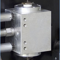
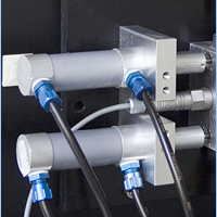
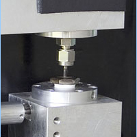
| Pneumatic injector | Measuring cell | Loading valve and draining valve | Pressure regulator |
|
|
|
|
|
Repeatability
- 5 mBa
Resolution
- 1 mBa
Internal Security
- Watch-dog
- By PC or interlock watch-dog default, the watch dog turn off the electrical power of all the components except the PC
Alarm Output
- Default analyser: 1 contact
- Low sample flow: 1 contact
- Low water flow: 1 contact
Input Signal
- 1 Contact, stand by, analysis cycle interrupted
- 1 Contact, start analysis, restart of an analysis cycle
Output Signal
- 4 to 20 mA accessible from the set-up linear module, galvanic separation, max load 600 Ohms
Cooling Devices
- Water cooled of the hot side of the Peltier element
- Lowest cell temperature –35°C (with cooling water at +10°C)
Ambient Conditions
- Temperature + 5°C to + 40°C
- HR 80% maximum
- No excess of dust or corrosive atmosphere
- Installation: analyser house or shelter
Radio Electric Perturbation
For all the standard frequencies don’t use radio at less than one meter ot the analyser
Classification
- Classification EEx p II B T 6 / according CENELEC 50016
- Option : EE × P II C T6
Fittings
- Input/output sampling tubing 4/6 mm
- Air supply ¼ and ¾” NPT female
- Gland PG 13 or PG 16
Enclosure
- Class IP 65
Special Options
- Serial line RS 422 Modbus protocol
- Calibration decade box, ISO 9002 for PT 100 (supplied with connectors)
- Reference sample for validation of the analyser
- Sampling conditioning system, according application
Procedure of Control Before Dispatch
- Electronic calibration
- Analytical calibration on reference certified samples
- Control of functionality on certified sample in sample loop with about 100 results
- Certificate supplied on the status of calibration and tests done
Usefulness
- The instrument is equipped with Peltier elements
- The cooling water can be supplied by an already existing water line or by external chillers (option available upon request)
- Sample conditioning at 0°C
- Pneumatic injector of 3 ml sample quantity
- Measuring cell at 37.8 °C with pressure sensor
- Loading valve, draining valve and sample depressurization in bottle
- Vacuum pump
- Control system for pneumatic valves and pressure regulator
- PT100 temperature probe for conditioning and measuring cell
Characteristics of the Sample
- Flow: 10…30 l/h in rinsing phase
- Consumption: 2 … 5 l/h, depending on analysis numbers
- Pressure: Min 0,3 bar / Max 0,6 bar
- Contamination
- Without solid particles > 10 microns
- Without acid and solvent presence
- Max 100 ppm of water
- Inlet temperature
- Max 35 °C


